Grid-Forming vs Grid-Following: The Firmware Decision Behind the Mandate

A grid-following inverter waits. It reads the voltage waveform already present on the line, locks onto its phase, and pushes current in time with it. Take away that reference waveform, and the inverter has nothing to follow. It rides through nothing, supports nothing, and within milliseconds its protection logic disconnects it. That single behavior, replicated across thousands of devices, is the design assumption regulators on three continents have now decided the grid can no longer afford.
For a decade, that assumption was perfectly reasonable. The grid was built around synchronous machines: coal, gas, hydro, and nuclear turbines whose spinning mass set the frequency and voltage that everything else referenced. Solar and storage were guests on that grid. They followed because there was always something solid to follow. The question of grid-forming vs grid-following was an academic distinction inside power-electronics labs, not a product decision on an OEM’s roadmap. That has changed, and it has changed in a way that lands squarely on the firmware your engineering team ships, not on the silicon they buy.
This is the part the hardware-spec sheets miss. The difference between a grid-following inverter and a grid-forming one lives mostly in the control loop, not the power electronics. And that means “add grid-forming” is rarely a setting your field engineers can flip. It is usually a firmware program, often a new product line, with a validation burden that dwarfs the cost of the hardware itself.
Two control philosophies, one grid: why grid-forming vs grid-following is now a product decision
Strip away the marketing and the two modes describe two opposite jobs.
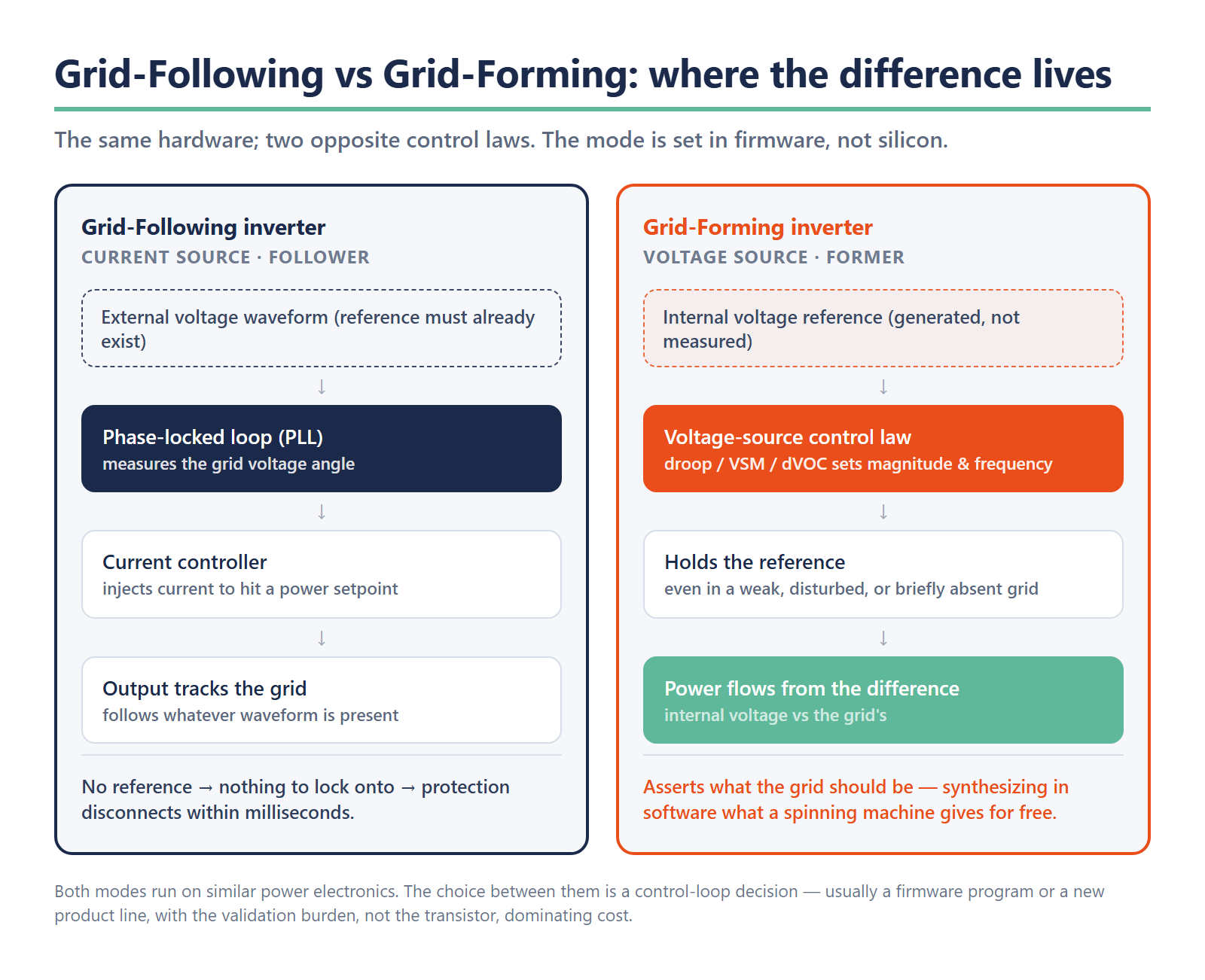
A grid-following inverter is a current source synchronized to an external reference. A phase-locked loop (PLL) measures the grid voltage angle, and the controller injects current to hit a target real- and reactive-power setpoint relative to that angle. It is fast, efficient, and well-understood. It is also fundamentally dependent: it assumes a stable voltage waveform already exists, and it behaves as a follower of that waveform. The overwhelming majority of solar inverters and battery systems deployed in the last fifteen years work this way.
A grid-forming inverter is a voltage source. Instead of locking onto an external angle, it generates its own internal voltage reference of defined magnitude and frequency, and it holds that reference even when the surrounding grid is weak, disturbed, or briefly absent. It does not wait to be told what the grid is doing. It asserts what the grid should be, and lets power flow follow from the difference between its internal voltage and the grid’s. That is the behavior a synchronous generator provides for free, by physics, through the inertia of its rotating mass. A grid-forming inverter has to synthesize the same behavior in software, in microseconds, with no flywheel to fall back on.
The two are not interchangeable firmware personalities sitting behind one menu toggle. They rest on different control architectures, different stability assumptions, and different protection philosophies. The table below frames the contrast at the level an engineering or product lead actually has to decide on.
| Dimension | Grid-Following Inverter | Grid-Forming Inverter |
|---|---|---|
| Control role | Current source — injects power against an existing reference | Voltage source — establishes the reference itself |
| Grid reference | Locks onto external voltage waveform via a phase-locked loop (PLL) | Generates its own internal voltage magnitude and frequency |
| Behavior in a weak or absent grid | Destabilizes or trips offline — has nothing to follow | Holds the reference and supports voltage and frequency |
| Inertial / fast support | None inherent | Synthesized in software (synthetic inertia, fast reactive response) |
| Primary engineering layer | Mature, well-understood control loop | Control-loop architecture, EMT model, weak-grid tuning |
| Mandate exposure | Increasingly non-compliant past high IBR penetration | Required by NC RfG 2.0 (>1 MW), enabling NERC PRC-029 ride-through |
The reason this distinction has graduated from a lab curiosity to a roadmap line item is that the grid those followers were designed for is disappearing underneath them.
Why grid-following hit its ceiling on a renewables-heavy grid
A grid-following inverter is only as stable as the reference it follows. When synchronous generation dominated, that reference was rock-solid: spinning mass resisted change, and frequency moved slowly enough that a follower always had something firm to lock onto. As inverter-based resources displace that spinning mass, the reference itself gets weaker, and the followers start destabilizing the very signal they depend on.
This is the heart of the weak-grid problem, and it is no longer theoretical. On 28 April 2025, the Iberian peninsula went dark in one of the largest blackouts in modern European history. ENTSO-E’s final report is careful and explicitly multi-factor, and it is worth quoting its restraint: the European network operators attribute the cascade to oscillatory instability and inadequate voltage and reactive-power control, and they conclude that even substantially higher system inertia, on its own, would not have prevented the loss of synchronism. The earlier factual report, published in October 2025, had already recorded grid-following plants tripping offline on overvoltage as the disturbance propagated, each disconnection removing support and pushing neighboring devices closer to their own trip thresholds.
The engineering lesson is not “renewables are unstable.” It is more specific and more useful: a population of inverters that can only follow has no collective ability to hold a reference when that reference starts to wander. Each device, behaving correctly by its own design, makes the aggregate worse. Past a certain penetration of inverter-based resources, following is a control philosophy that runs out of road. Something on the grid has to form, which is why grid resilience has turned into a controls-software problem rather than a hardware-procurement one.
That realization is what turned grid-forming from a research topic into a regulatory obligation. The EU’s revised Requirements for Generators network code (NC RfG 2.0), finalizing through 2026, introduces a grid-forming obligation for new plants above roughly one megawatt. In the United States, NERC’s PRC-029-1 ride-through standard, approved by FERC Order 909 in July 2025, becomes effective on 1 October 2026 and forces inverter-based resources to stay connected and supportive through exactly the kind of voltage and frequency excursions that tripped the Spanish fleet. IEEE 2800.2-2026 supplies the conformance framework underneath. The direction is set, and it is dated. Operators are not waiting for the standards to mature before they act; Australia’s market operator, AEMO, reported ten grid-forming battery sites totaling 1,070 megawatts already operational as of December 2025. Grid-forming is deployable today, at fleet scale, on real networks.
For an OEM, the takeaway is uncomfortable but clear. Mandates of this kind do not ask whether your inverter is fast or efficient. They ask whether it can form. And forming is a control-loop capability.
What “forming” actually demands inside the control loop
When a product team asks “can our platform do grid-forming,” the honest answer starts with another question: which forming control law, and tuned for which grid conditions? “Grid-forming” is a family of control strategies, not a single feature, and the choice among them shapes the entire validation and integration program that follows.
Three approaches dominate the field today, and a product lead should understand them at a decision level even if the detailed implementation belongs to the power-electronics team.
Droop control is the simplest. It mimics a synchronous generator’s natural behavior by adjusting output frequency in proportion to real power and voltage in proportion to reactive power. It is robust and well-proven, but its response is comparatively slow and it offers no inherent inertial response to fast transients.
Virtual synchronous machine (VSM) control goes further by emulating the full swing equation of a rotating generator, including a synthetic inertia constant and damping. It delivers an inertial response a droop controller cannot, at the cost of more complex tuning and a model that can itself become a source of oscillation if mismatched to the grid.
Dispatchable virtual oscillator control (dVOC) is the newest of the three. Rather than emulating a machine, it drives the inverter as a nonlinear oscillator that synchronizes with its neighbors, offering strong theoretical stability guarantees and fast response, with a steeper learning curve and a thinner field-deployment track record than the older approaches.
The decision among these is not cosmetic. It propagates into your control hardware requirements, your protection coordination, your electromagnetic-transient (EMT) simulation models, and the test regime every grid operator will demand before energizing your asset. The table below lays out the trade space.
| Control approach | How it works | Strengths | Trade-offs for the OEM |
|---|---|---|---|
| Droop control | Adjusts frequency with real power and voltage with reactive power, mimicking a generator’s natural response | Robust, well-proven, simplest to tune | Slower response; no inherent inertial reaction to fast transients |
| Virtual synchronous machine (VSM) | Emulates the full swing equation of a rotating generator, including synthetic inertia and damping | True inertial response; familiar machine-like behavior | More complex tuning; the emulation model itself can oscillate if mismatched to the grid |
| Dispatchable virtual oscillator control (dVOC) | Drives the inverter as a nonlinear oscillator that synchronizes with neighboring units | Strong stability guarantees; fast response | Steeper learning curve; thinner field-deployment track record |
There is a second layer the spec sheets rarely surface. A grid-forming control law that behaves beautifully in a strong, stiff network can go unstable in a weak one with a low short-circuit ratio, exactly the conditions where forming matters most. Tuning for weak-grid stability is its own discipline, and it is where many promising prototypes stall between the bench and the field. This is also why the UNIFI Consortium’s grid-forming specification, now at version 3, exists at all: the industry needed a common functional definition because “grid-forming” had come to mean too many different things across too many vendors.
For the OEM, all of this lives in firmware and validation. None of it is solved by a better transistor.
Retrofit or new product line? Why “add grid-forming” is usually a firmware program
The most expensive misconception in this transition is that grid-forming is a firmware patch you can push to an installed fleet. It is occasionally true. It is usually not, and the difference depends on decisions made years before the mandate landed.
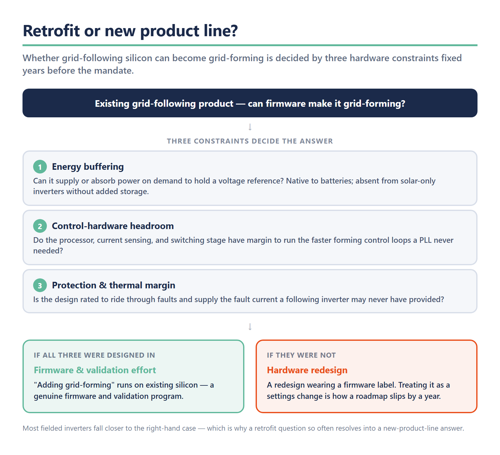
Whether an existing grid-following product can become grid-forming through firmware comes down to whether the underlying hardware was ever architected for it. Three constraints decide the answer. First, energy buffering: a grid-forming source must supply or absorb power on demand to hold its voltage reference, which a battery can do natively but a solar-only inverter cannot without storage behind it. Second, control-hardware headroom: grid-forming control loops run faster and demand more from the processor, the current sensing, and the switching stage than a follower’s PLL ever did. Third, protection and thermal margin: a forming inverter must ride through faults and supply fault current that a grid-following design may never have been rated for.
Where those three were anticipated, “adding grid-forming” can genuinely be a firmware and validation effort on existing silicon. Where they were not, it is a hardware redesign wearing a firmware label, and treating it as a settings change is how a roadmap slips by a year. Most fielded inverters fall closer to the second case than the first, which is precisely why a retrofit question so often resolves into a new-product-line answer.
But the firmware itself is the smaller half of the program. The larger half is what comes after the control law works on the bench.
Why the OEM’s real cost lives in validating and integrating the mode across a fleet
Here is the line item that surprises product teams. The control law is hard, but it is finite. The validation and integration that turn a working control law into a deployable, compliant, fleet-wide capability is the part that consumes the schedule and the budget.
Three obligations drive that cost. The first is EMT model validation. Every grid operator now requires an electromagnetic-transient model of your inverter’s grid-forming behavior, validated against hardware tests, before they will let the asset energize. That model has to match the device’s measured response across the full envelope of disturbances the grid code specifies, and producing and maintaining it is a sustained engineering effort, not a one-time deliverable. The same compliance burden that turned interconnection into a software exercise for distributed resources, a pattern Codibly has documented in its work on IEEE 2030.5 implementation pitfalls for DER manufacturers, now extends to the dynamic behavior of the inverter itself.
The second is multi-region certification. NC RfG 2.0, NERC PRC-029, IEEE 2800.2, and the country-by-country test regimes underneath them do not align cleanly. A single product sold across the EU, the US, and Australia faces overlapping but non-identical requirements, each with its own studies, test points, and documentation. This is the same state-by-state fragmentation OEMs already know from interconnection mandates such as Colorado’s statewide IEEE 1547 adoption, now reproduced at the grid-code layer and on a global scale.
The third, and the most underestimated, is fleet integration. A grid-forming asset does not run alone. It coordinates with a battery management system, a power-conversion system, and a plant or energy-management controller, and the boundaries between those layers are where deployments actually stall: time-synchronization, control-hierarchy arbitration, and clean telemetry up to the operator. The orchestration software that decides when and how a fleet of forming assets responds, the layer above the firmware, is doing work the inverter control loop alone cannot. It is the same architectural problem Codibly addresses in the energy-management layer that decides what a battery actually does.
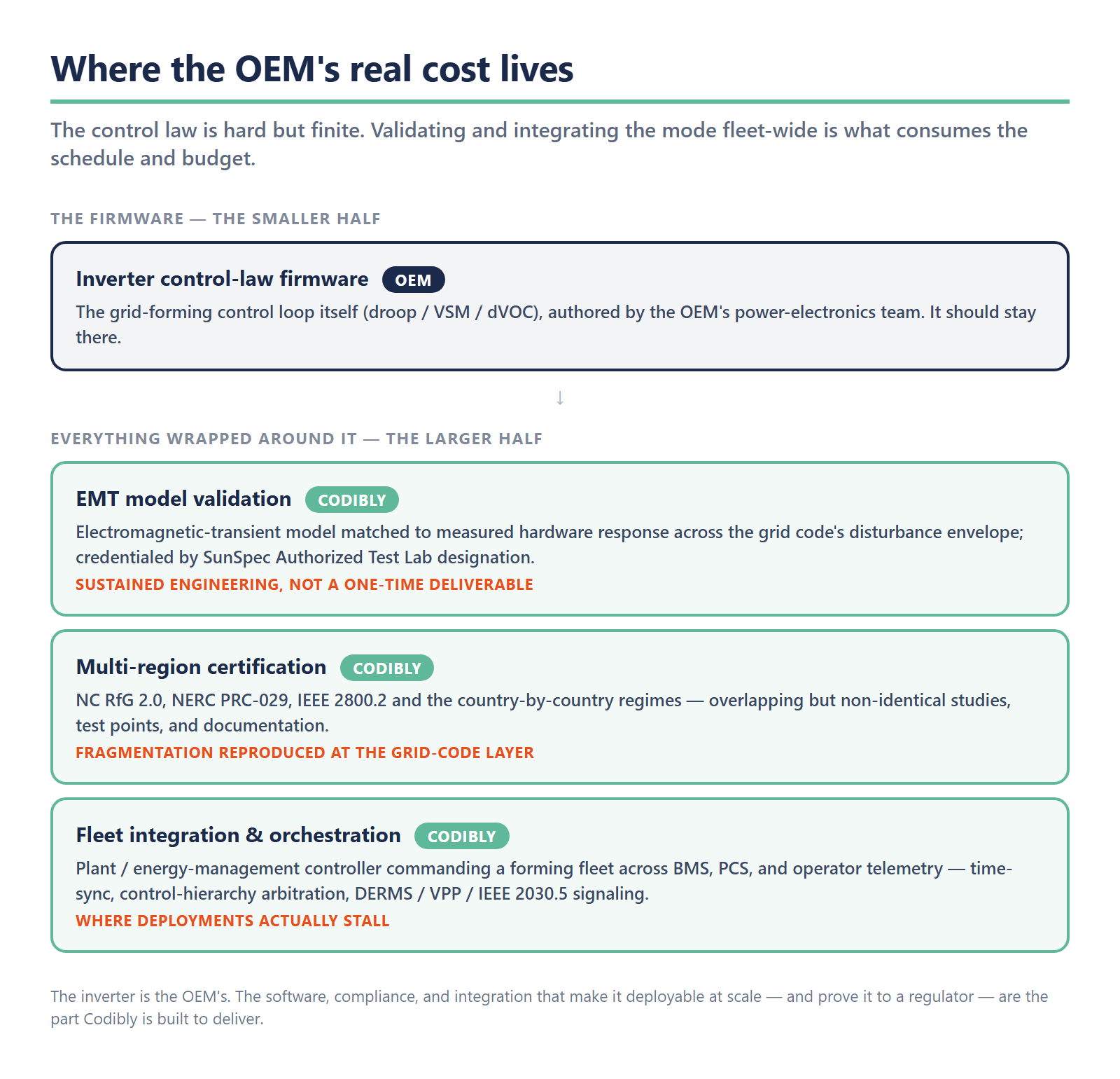
This is where the Codibly lens comes into focus. Codibly does not author inverter control-law firmware; that is the OEM’s power-electronics team, and it should stay there. What an OEM repeatedly needs is everything wrapped around that firmware: the EMT-validation and grid-code-study toolchain, credentialed by Codibly’s SunSpec Authorized Test Lab designation; the plant-controller and EMS software that commands a grid-forming fleet; and the integration into DERMS, VPP, and operator-signaling environments through standards like IEEE 2030.5. The inverter is the OEM’s. The software, compliance, and integration that make it deployable at scale and prove it to a regulator are the part Codibly is built to deliver.
The decision behind the mandate
Underneath every grid-forming mandate is a single, unglamorous engineering decision: whether your product forms voltage or follows it. That decision is made in the control loop, validated in EMT models, and proven across a fleet, and it determines whether your hardware is sellable in three of the world’s largest markets after the deadlines arrive.
The temptation is to treat it as a hardware question and answer it with a spec sheet. The grid that is emerging, and the regulators writing rules for it, have already decided otherwise. Forming is a software capability with a validation tail, and the OEMs that win the next phase of the energy transition will be the ones that treat it as a deliberate firmware and product program rather than a setting to flip when a customer asks. The deadline risk in standards like PRC-029 cuts in one direction only: it rewards the teams that started early. The question on the table for every inverter and storage OEM is no longer whether grid-forming is coming. It is whether your roadmap, your validation capacity, and your integration software are ready to form when the mandate says they must. That readiness is buildable today, and it is exactly the kind of renewable-energy compliance and integration work Codibly partners with OEMs to deliver.
Frequently Asked Questions
A grid-following inverter is a current source that synchronizes to a voltage waveform already present on the grid, using a phase-locked loop to lock onto the grid’s phase and inject power in time with it. It depends on an external reference and cannot operate without one. A grid-forming inverter is a voltage source that generates its own internal voltage and frequency reference and holds it even when the surrounding grid is weak or briefly absent, behaving like the synchronous generators it is replacing. The core difference is not the power electronics but the control loop: one follows an existing reference, the other forms one.
Sometimes, but it is rarely a simple firmware update. Whether a retrofit is possible depends on whether the original hardware was architected for grid-forming duty. It needs an energy buffer to supply or absorb power on demand (native to batteries, but absent from solar-only inverters without added storage), enough control-hardware and processing headroom to run the faster grid-forming control loops, and adequate protection and thermal margin to ride through and supply fault current. Where those were designed in, grid-forming can be a firmware and validation effort. Where they were not, “adding grid-forming” becomes a hardware redesign, which is why the question often resolves into a new product line rather than a settings change.
A grid-following inverter is a follower by design: it measures an existing grid voltage waveform and synchronizes to it. With no reference waveform present, it has nothing to lock onto, so it cannot establish voltage or frequency and its protection logic disconnects it. A grid composed only of followers has no device asserting the reference everything else tracks, so when that reference drifts, each inverter’s correct individual behavior degrades the collective signal rather than stabilizing it. Running a grid, especially through disturbances or in a weak network, requires at least some assets that form voltage and frequency rather than follow them, which is the role grid-forming inverters and synchronous machines play.