When the Grid Stops Spinning: Why Grid-Forming Is a Software Problem

Executive Summary
At 12:33 on 28 April 2025, the Iberian Peninsula lost synchronism with the rest of continental Europe and went dark. Within seconds, roughly 60 percent of Spain’s electricity demand was gone, and most of Portugal followed. The reflex explanation circulated immediately: too much solar, not enough spinning iron. ENTSO-E’s investigation told a more uncomfortable story. The cascade was driven by oscillatory instability and inadequate voltage and reactive-power control, and the analysis concluded that even substantially higher system inertia, on its own, would not have prevented the loss of synchronism.
That distinction reframes the entire resilience conversation. For a century, grid stability was a property of physics: thousands of synchronous generators, their massive rotors spinning in lockstep at 50 or 60 hertz, absorbing shocks through sheer rotational mass. As those machines retire and inverter-based resources carry the load, that physical buffer thins out. The grid no longer holds itself up by inertia. It has to be told how to behave, in software, microsecond by microsecond.
This paper argues that grid resilience has become a controls-software problem rather than a hardware-procurement one, and that the mandate wave following Iberia has made that shift binding on three continents at once. The United States wrote ride-through obligations into NERC PRC-029, effective 1 October 2026 under FERC Order 909. The European Union is finalizing a grid-forming obligation for new plants above 1 megawatt under Network Code RfG 2.0. IEEE 2800.2-2026 published conformance test procedures for inverter-based resources, and the UNIFI Consortium released its third-generation grid-forming specification. The direction is set and the deadlines are dated.
The decisive capability is no longer building the cheapest inverter. It is the ability to implement, integrate, and validate grid-forming behavior across heterogeneous fleets of inverters and batteries, then prove that behavior to a regulator. That is a software-delivery discipline. For DER hardware original equipment manufacturers (OEMs) and grid operators alike, the procurement question has already changed from “does this asset meet spec” to “can we orchestrate and certify this fleet’s grid-forming response at portfolio scale.” This paper maps that surface and where deployments actually stall.
| Stabilizing function | How a synchronous machine provided it | How it is provided in an inverter-based grid |
|---|---|---|
| Inertia (arresting fast frequency change) | Automatic, from rotating mass | Synthetic / virtual inertia, computed and injected by grid-forming control software |
| Voltage / frequency reference | The spinning machine is the reference | Grid-forming inverter imposes its own reference via control law |
| Fault ride-through | Inherent to the machine’s physics | Engineered behavior, configured and validated per grid code |
| Behavior during disturbance | Rides through by inertia | Depends entirely on control law and fleet orchestration; grid-following units may trip |
| Coordination across assets | Implicit, all machines share one physical frequency | Explicit, requires plant control, telemetry, and arbitration software |
The day the Iberian grid stopped: read it as a warning
The temptation after any large blackout is to file it under bad luck. A rare alignment of faults, a once-in-a-decade coincidence, a system pushed past a line nobody will cross again. Iberia resists that filing.
What the post-mortems describe is not an exotic failure mode. ENTSO-E’s factual report, published 3 October 2025, documented grid-following inverters tripping offline on overvoltage as conditions deteriorated, withdrawing support at the precise moment the system needed it most. The final report, issued in March 2026, set that detail inside a systemic frame: voltage and reactive-power control across the peninsula was inadequate for the operating conditions, and the resulting oscillations drove the network out of step. The agency was careful, and correct, to call it multi-factor. There is no single switch that, flipped, would have kept the lights on. But the through-line is unmistakable. A grid increasingly run by inverters behaved in ways its operators could not arrest, because the control behavior of those inverters was reactive by design.
That is the warning. Iberia is not the last grid on earth where synchronous generation is thinning while inverter penetration climbs. It is among the first to cross the threshold where the old physical buffer ran out before the new software behavior was in place. Texas, South Australia, Ireland, the Nordic synchronous area, and large swaths of the German and Dutch networks are on the same trajectory, some further along than Iberia was. The question every system operator now faces is not whether their grid will reach that threshold. It is whether the inverter fleet riding on it will hold the grid up or let go.
Reading Iberia as an anomaly invites the wrong remedy: build more reserve, add more iron, treat the event as a capacity shortfall. Reading it as a warning points at the real gap. The assets were there. The control behavior was not.
Why replacing spinning machines with inverters is a control problem
To see why software now sits at the center of resilience, it helps to be precise about what the retiring machines actually did, beyond making power.
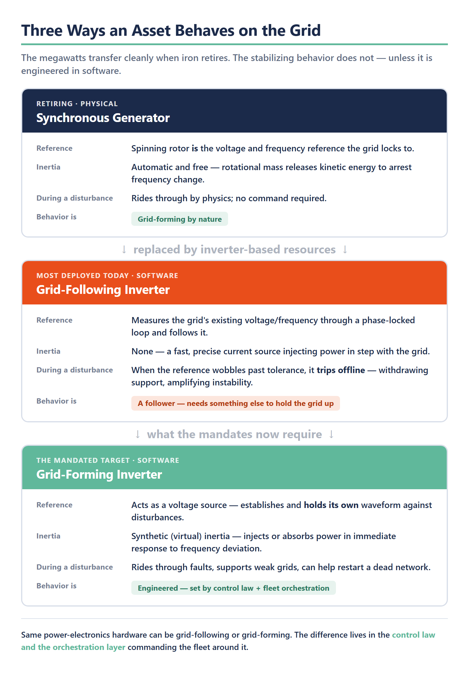
A synchronous generator is a heavy rotating mass turning in fixed relationship with grid frequency. When demand suddenly exceeds supply, that rotor does not wait for a command. Physics slows it down, and in slowing it releases kinetic energy into the grid, arresting the frequency drop in the first fractions of a second. This is inertia, and it is free, automatic, and analog. The machine also sets the voltage waveform itself, acting as a stiff reference that everything else on the network synchronizes to. A spinning generator is, in effect, a grid-forming device by its nature.
Most inverters deployed to date are not. A grid-following inverter is a fast, precise current source that measures the grid’s existing voltage and frequency through a phase-locked loop and injects power in step with it. It is excellent at pushing solar or battery energy onto a healthy grid. It is, by construction, a follower, and whether it can ever be made to form voltage instead is a firmware decision, not a hardware one. It needs a stable reference to lock onto, and when that reference wobbles past its tolerances, its protective instinct is to disconnect. Multiply that instinct across a peninsula’s worth of inverters during a disturbance, and the followers amplify the very instability they were meant to ride through.
A grid-forming inverter inverts that logic. Rather than chasing an external reference, it behaves as a voltage source, establishing its own frequency and voltage waveform and holding it against disturbances, the way a synchronous machine does. It can provide synthetic inertia, often called virtual inertia, by injecting or absorbing power in immediate response to frequency deviations. It can support a weak grid, ride through faults instead of tripping, and in the limit help restart a dead network. The hardware to do this, fast switches, capable power stages, sufficient headroom, increasingly exists across the inverter and battery market. What turns that hardware into grid-forming behavior is the control law running on it and the orchestration layer commanding the fleet around it.
That is the pivot. Swapping a gas turbine for a solar farm plus storage is not a like-for-like generation swap. It removes a physical control behavior the grid silently depended on and replaces it with one that has to be engineered, configured, validated, and coordinated. The megawatts transfer cleanly. The stabilizing behavior does not transfer at all unless someone builds it.
Why grid resilience is now a controls-software problem
Here the argument has to be careful, because the strongest objection to it is also partly right. Grid-forming begins in power electronics. The inner control law, droop, virtual synchronous machine emulation, or dispatchable virtual oscillator control, lives in firmware authored by the OEM’s power-electronics team, close to the silicon and the switching. No software-integration partner should claim to write that loop, and nothing here does.
The claim is narrower and, for a buyer, more consequential. The control law is necessary and nowhere near sufficient. A grid-forming inverter that performs flawlessly on a test bench delivers no resilience until it is configured for the specific impedance of the grid it sits on, coordinated with every other asset at the same point of connection, arbitrated against the battery management and plant-control hierarchy above it, validated against the regulator’s electromagnetic transient model, and orchestrated across a fleet that may span dozens of sites and multiple market regions. Each of those is a software and systems-integration problem. None of them is solved by a better switch.
Field evidence keeps pointing at the same place. Industry reporting through 2025, including detailed accounts in POWER Magazine, converges on commissioning and integration as where grid-forming storage projects actually stall — the same class of integration burden that surfaces when DER manufacturers implement protocol conformance: battery management system to power conversion system to energy management system interoperability, time synchronization across controllers, arbitration of competing control hierarchies, and electromagnetic transient model validation. These are not nameplate shortcomings. The inverters meet spec. The systems wrapped around them do not yet behave as a coordinated whole.
The most persuasive counter-evidence runs the same direction. The Australian Energy Market Operator reported on 5 December 2025 that ten grid-forming battery sites totaling 1,070 megawatts were operational on its network. That is the strongest available proof that this is deployable today rather than a research roadmap. It is also a fleet, ten coordinated installations behaving as grid infrastructure, which is precisely a software-orchestration achievement, not a procurement one. Nobody reaches 1,070 megawatts of stabilizing capacity by buying better inverters. They reach it by making heterogeneous assets act in concert and proving that they do.
Resilience, in other words, has moved up the stack. It used to be a property of the machines. It is now a property of the software that commands them.
The mandate wave is now binding, and the deadline rewards acting early
For several years grid-forming was a recommendation, a design preference advanced by researchers and forward-leaning operators. Iberia accelerated its conversion into law, and the timeline is now specific enough to plan against.
In the United States, NERC reliability standard PRC-029-1 establishes ride-through requirements for inverter-based resources. FERC approved it through Order 909 on 24 July 2025, with an effective date of 1 October 2026. IEEE 2800-2022 set the interconnection requirements for inverter-based resources, and IEEE 2800.2-2026 published the conformance test procedures that turn those requirements into something a project must demonstrate, not merely assert. The UNIFI Consortium’s grid-forming specification, now in its third version, gives OEMs and operators a converging technical target for what “grid-forming” concretely means. In the European Union, Network Code RfG 2.0 is being finalized through 2026 with a grid-forming obligation for new plants above 1 megawatt, layered over existing connection codes such as EN 50549. Australia, having lived the inverter-grid future earliest, is already operating fleets at scale under its own market rules.
| Instrument | Region | What it requires of inverter-based resources | Status / effective date |
|---|---|---|---|
| NERC PRC-029-1 (via FERC Order 909) | United States | Ride-through behavior for inverter-based resources | Approved 24 Jul 2025; effective 1 Oct 2026 |
| IEEE 2800-2022 / 2800.2-2026 | United States (reference, adopted widely) | Interconnection requirements (2800) and conformance test procedures (2800.2) for IBRs | 2800 published 2022; 2800.2 conformance published 2026 |
| UNIFI Consortium Specification v3 | United States / international | Converging technical definition of grid-forming behavior | Version 3 released 2026 |
| Network Code RfG 2.0 | European Union | Grid-forming obligation for new plants above 1 MW | Finalizing through 2026 |
| EN 50549 | European Union | Connection requirements for generating plants | In force; layered with RfG 2.0 |
| AEMO market rules | Australia | Operating grid-forming BESS fleets at scale | 10 sites / 1,070 MW operational (5 Dec 2025) |
A reasonable skeptic will note that US energy policy has been volatile, and that mandates sometimes slip. Fair. But PRC-029 is approved and dated, not proposed, and RfG 2.0 is in finalization rather than consultation. When the regulatory direction is set and the cheapest path to compliance runs through software that takes quarters to build and validate, the deadline risk cuts in one direction. It rewards moving early. An OEM that treats grid-forming and its conformance evidence as a product-line program starting now has time to validate properly. One that waits for the rule to bite discovers that compliance cannot be retrofitted into a fleet, a controller, or a validation pipeline that was never architected for it.
That is the asymmetry strategic buyers should weigh. The upside of acting before the deadline is an orderly, validated rollout and unobstructed market access across regions. The downside of waiting is a scramble against a fixed date with a fleet already in the field, where every fix is more expensive and slower than it would have been in design.
The implementation surface OEMs and operators keep underestimating
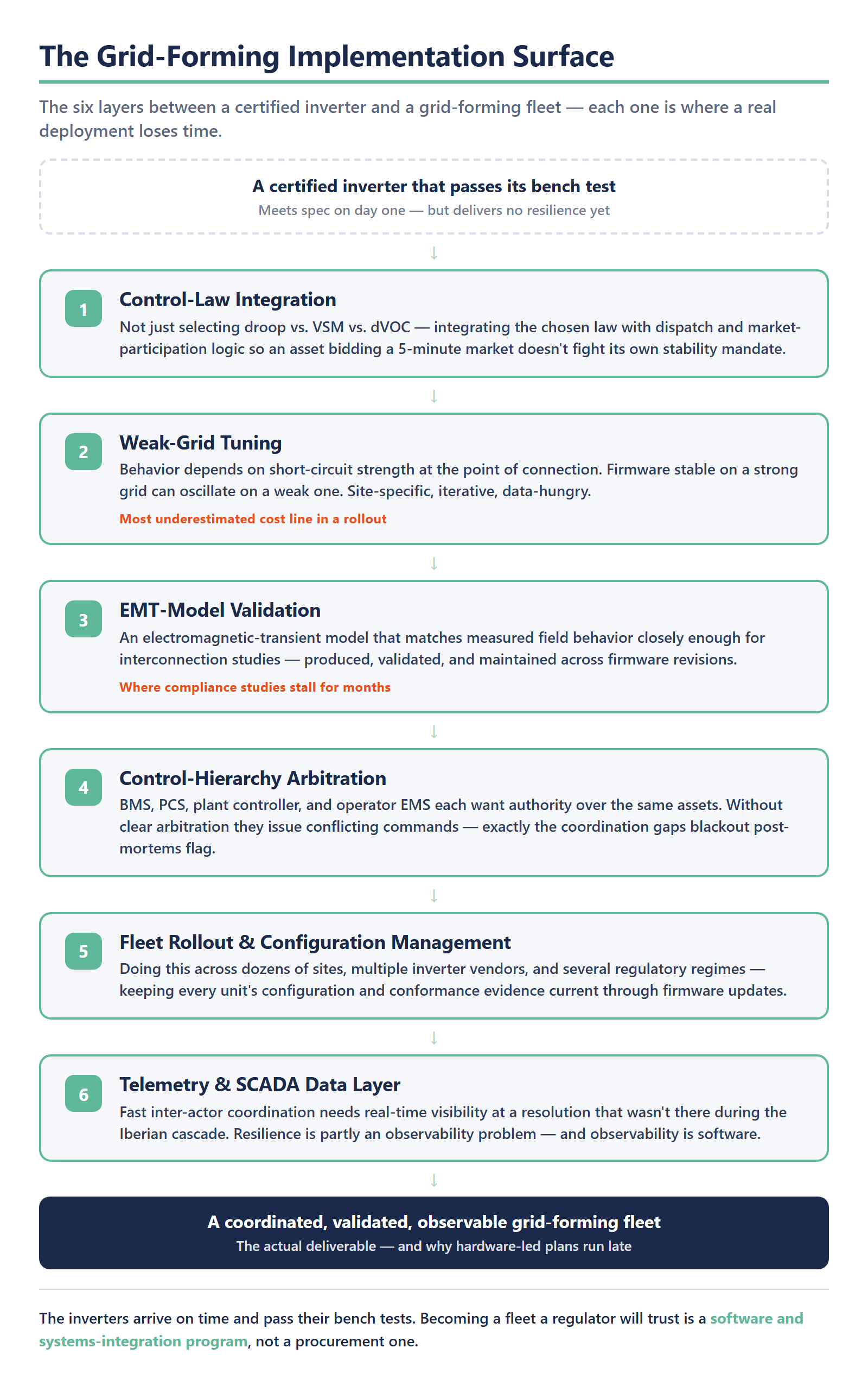
The gap between a certified inverter and a grid-forming fleet is wider than most procurement plans assume, and it is worth naming the surface in full, because each layer is where a real deployment loses time.
Control-law integration, not just selection. Choosing droop versus virtual synchronous machine emulation versus dispatchable virtual oscillator control is the visible decision. The harder work is integrating whichever law is chosen with the dispatch and energy-optimization logic above it, so that an asset bidding into a five-minute market does not fight its own stability mandate.
Weak-grid tuning. A grid-forming inverter’s behavior depends heavily on the short-circuit strength at its point of connection. The same firmware that is stable on a strong grid can oscillate on a weak one. Tuning is site-specific, iterative, and data-hungry, and it is one of the most underestimated cost lines in any rollout.
Electromagnetic transient (EMT) model validation. Regulators and transmission operators increasingly require an EMT model of the resource that matches its measured field behavior closely enough to trust in interconnection studies. Producing, validating, and maintaining that model across firmware revisions is a discipline in its own right, and it is frequently the step where compliance studies stall for months. That is the point at which grid-code compliance becomes a software deliverable rather than a paper assurance.
Control-hierarchy arbitration. On a real site, the battery management system, the power conversion system, the plant controller, and the operator’s energy management system each want authority over the same assets. Without clear arbitration, they issue conflicting commands. The blackout post-mortems repeatedly flagged coordination gaps of exactly this kind.
Fleet rollout and configuration management. Doing this once for one site is an engineering exercise. Doing it across dozens of sites, multiple inverter vendors, and several regulatory regimes, while keeping every unit’s configuration and conformance evidence current through firmware updates, is a software-platform problem.
The telemetry and SCADA data layer. The Iberian analysis underscored how thin the real-time visibility was between actors during the cascade. Faster inter-actor coordination depends on a telemetry and supervisory control and data acquisition layer that simply was not there at the resolution required. Resilience is partly an observability problem, and observability is software.
Read together, this list explains why hardware-led plans run late. The inverters arrive on time and pass their bench tests. The fleet that those inverters are supposed to become takes far longer, because becoming a coordinated, validated, observable fleet is the actual deliverable.
What it takes to deliver and validate grid-forming at portfolio scale
This is where the work concentrates, and where Codibly’s renewable-energy engineering scope sits. Codibly does not manufacture inverters, and it does not author the inner control-law firmware that belongs to an OEM’s power-electronics team. The software layer around grid-forming is the discipline, and it has four parts that together turn capable hardware into certified, coordinated grid infrastructure.
The first is the plant-controller and energy-management software that commands and coordinates grid-forming batteries and inverter fleets, resolving the control-hierarchy arbitration described above so that battery management, power conversion, plant control, and energy management act as one system rather than four competing ones. This is the same kind of control stack that decides whether a battery earns its keep, applied to stability instead of arbitrage: the layer that lets ten sites behave as 1,070 megawatts of coordinated capacity rather than ten isolated installations.
The second is the compliance-implementation and validation toolchain: the grid-code studies, EMT-model validation, and conformance evidence that a regulator will accept. Codibly’s designation as a SunSpec Authorized Test Lab, granted in March 2026, credentials exactly this work, the validation and certification path that converts grid-forming behavior into market access. The pattern is established. In delivering IEEE 2030.5 development and certification for a battery storage provider under California’s Rule 21, Codibly used its IEEE 2030.5 accelerator to reach certification in eight weeks, treating the compliance pathway as an engineered software deliverable rather than a paperwork afterthought. Grid-code conformance for grid-forming resources is the same discipline applied to a harder regulatory surface.
The third is integration of grid-forming assets into the platforms that operators actually run: DER management systems, virtual power plants, and the distribution and transmission operator signaling that coordinates them. Codibly built a custom DERMS platform for the retail energy provider APG&E, delivering an end-to-end orchestration workflow with real-time telemetry and a standards-ready path for OpenADR and IEEE 2030.5, in twelve weeks. Grid-forming assets are the next class of resource that orchestration layer must command.
The fourth is the telemetry and data layer the blackout post-mortems flagged as missing, the real-time observability that lets operators see and coordinate fast enough to arrest a disturbance rather than document it afterward.
| Layer | Owner | What it does |
|---|---|---|
| Inverter hardware & inner control-law firmware | OEM power-electronics team | Droop / VSM / dVOC control loop on the silicon |
| Plant controller / energy management software | Codibly | Commands and coordinates fleets; arbitrates BMS / PCS / plant / EMS hierarchy |
| Compliance-implementation & validation toolchain | Codibly (SunSpec Authorized Test Lab) | Grid-code studies, EMT-model validation, conformance evidence for market access |
| DERMS / VPP / DSO-TSO integration | Codibly | Integrates grid-forming assets into orchestration platforms and operator signaling |
| Telemetry / SCADA data layer | Codibly | Real-time observability for fast inter-actor coordination |
None of this displaces the OEM’s hardware or its control law. It is the layer that makes the hardware deployable, certifiable, and coordinated at the scale the mandates now require. The buyer this serves is not someone shopping for inverters. It is the OEM or operator who already has the hardware and needs the software, compliance, and integration to field it across a portfolio and prove it to a regulator.
The grid that forms itself is a software deliverable now
The Iberian grid did not fail because Spain installed too much solar. It failed because, at the moment that mattered, the assets carrying the network were built to follow a reference that was no longer there, and nothing was built to form one in their place. That is a controls gap, and controls gaps are closed in software.
The mandates have absorbed that lesson and made it binding. PRC-029 takes effect in October 2026, RfG 2.0 is finalizing for new plants above 1 megawatt, IEEE 2800.2 and the UNIFI specification have set the conformance target, and Australia is already operating grid-forming fleets above a gigawatt. The hardware to comply is increasingly available. The constraint has moved to whether an organization can configure, integrate, validate, and orchestrate that hardware into a fleet a regulator will trust, on the timeline a fixed deadline allows.
For DER OEMs and grid operators, the practical implication is a reframed procurement question. The right question is no longer which inverter clears the spec sheet. It is whether the software stack around that inverter can deliver grid-forming behavior across a heterogeneous portfolio, prove it through validated models and conformance evidence, and coordinate it in real time when a disturbance arrives. A grid that forms its own voltage and frequency is no longer a physics inheritance from spinning machines. It is something an organization now has to build, and what it builds it in is software. The firms that internalize that early will spend the run-up to the deadline validating. The firms that treat it as a hardware refresh will spend it scrambling.
Frequently Asked Questions
A grid-forming inverter is a power-electronic converter that behaves as a voltage source, establishing and holding its own voltage and frequency reference rather than measuring and following an existing one. That lets it perform functions a synchronous generator used to provide automatically: setting the grid’s waveform, supplying synthetic inertia in response to frequency deviations, supporting weak grids, riding through faults, and in some cases helping restart a network from a blackout. The distinction matters because most inverters deployed to date are grid-following, designed to inject power onto a grid that something else is holding stable.
A grid-following inverter uses a phase-locked loop to track the grid’s existing voltage and frequency, then injects current in step with that reference. A grid-forming inverter reverses the logic. It runs a control law, commonly droop control, virtual synchronous machine emulation, or dispatchable virtual oscillator control, that lets the inverter act as a stiff voltage source and impose its own waveform, adjusting power output in immediate response to disturbances. The hardware involved is broadly similar to a grid-following unit; the difference lives in the control software and in the orchestration layer that coordinates many such units into a coherent fleet.
The clearest near-term signal is deployment rather than a single market-size figure, and the trajectory is steep. The Australian Energy Market Operator reported ten grid-forming battery sites totaling 1,070 megawatts operational on its network as of 5 December 2025. With the European Union finalizing a grid-forming obligation for new plants above 1 megawatt under Network Code RfG 2.0, the United States enforcing inverter ride-through under NERC PRC-029 from 1 October 2026, and IEEE 2800.2 and the UNIFI specification setting conformance targets, the binding capability is shifting from optional to required across major markets. Demand is being created by mandate, which makes the addressable surface less a question of voluntary adoption and more a function of how much new inverter-based capacity those regions interconnect.
The control law that makes an inverter grid-forming begins in power electronics, authored by the hardware manufacturer, but a certified inverter delivers no resilience on its own. It has to be tuned to the short-circuit strength of the grid it sits on, arbitrated against the battery-management, power-conversion, and plant-control systems that share authority over the same assets, validated against the regulator’s electromagnetic transient model, and orchestrated across a fleet that may span dozens of sites and several market regions. Each of those is a software and systems-integration task, not a hardware one. That is why a fleet like the 1,070 megawatts now operating in Australia is an orchestration achievement rather than a procurement one: the megawatts transfer cleanly when spinning machines retire, but the stabilizing behavior has to be engineered in software.