Where the IEEE 2030.5 Protocol Actually Lives — How the Standard Settled into Production Systems

When utilities, aggregators, and OEMs talk about IEEE 2030.5, the conversation usually gravitates to certification: did the device pass the SunSpec test suite? Did the integration earn its CSIP credentials? Important questions, but they obscure a more useful one. Once compliance is done, where does the 2030.5 protocol actually run?
The answer, drawn from years of field deployments and from the recent SunSpec Alliance × Codibly webinar, is more practical than the spec sheets suggest. The standard works hardest at one specific seam — the boundary between the utility back office and the aggregator client — and that boundary, not the inverter terminal, is where most production traffic flows.
This piece walks through how that topology settled, why California’s Rule 21 helped shape it, what the server and client sides of the boundary actually look like in production, and where the per-utility customization sits on top of CSIP. The argument is not that native compliance at the device is wrong. It is that the deployment patterns Codibly sees in the field tell a more nuanced story about how the IEEE 2030.5 standard supports DER interoperability once compliance is in the rear-view mirror.
The Deployment Pattern Most Spec Sheets Don’t Show You
CSIP, the Common Smart Inverter Profile, was originally conceived to apply at the inverter level. The intent of the SunSpec working group was for inverter manufacturers to embed a 2030.5 client directly inside the device. That intent ran into a definition problem as implementations rolled out. What exactly counted as native support? The spec was less explicit on that point than many first readers assumed.
California opened up a second pathway under E5000. Manufacturers seeking compliance under Rule 21 could either implement a native 2030.5 CSIP interface inside the inverter, or perform interoperability testing against a CSIP-certified gateway at a nationally recognized test lab. Both routes counted. Both produced approved-equipment-list entries.
In practice, the second route became dominant. More than 80 percent of inverter manufacturers passed via the gateway-attestation path rather than embedding a 2030.5 client at the device. That single statistic, surfaced on the SunSpec × Codibly session, is the most useful starting point for anyone designing or evaluating a deployment today. It says less about the standard than about the topology that emerged: in the dominant deployed pattern, IEEE 2030.5 lives at the gateway and at the aggregator, not at the inverter terminal.
2030.5 Standardizes One Boundary — Everything Else Is Integration
The clearest way to understand the deployment is to look at where the protocol is actually defined, and where it is intentionally not. IEEE 2030.5 specifies the conversation between the utility’s back-office systems and a 2030.5 client. It does not specify what happens south of that client. That negative space is the design.
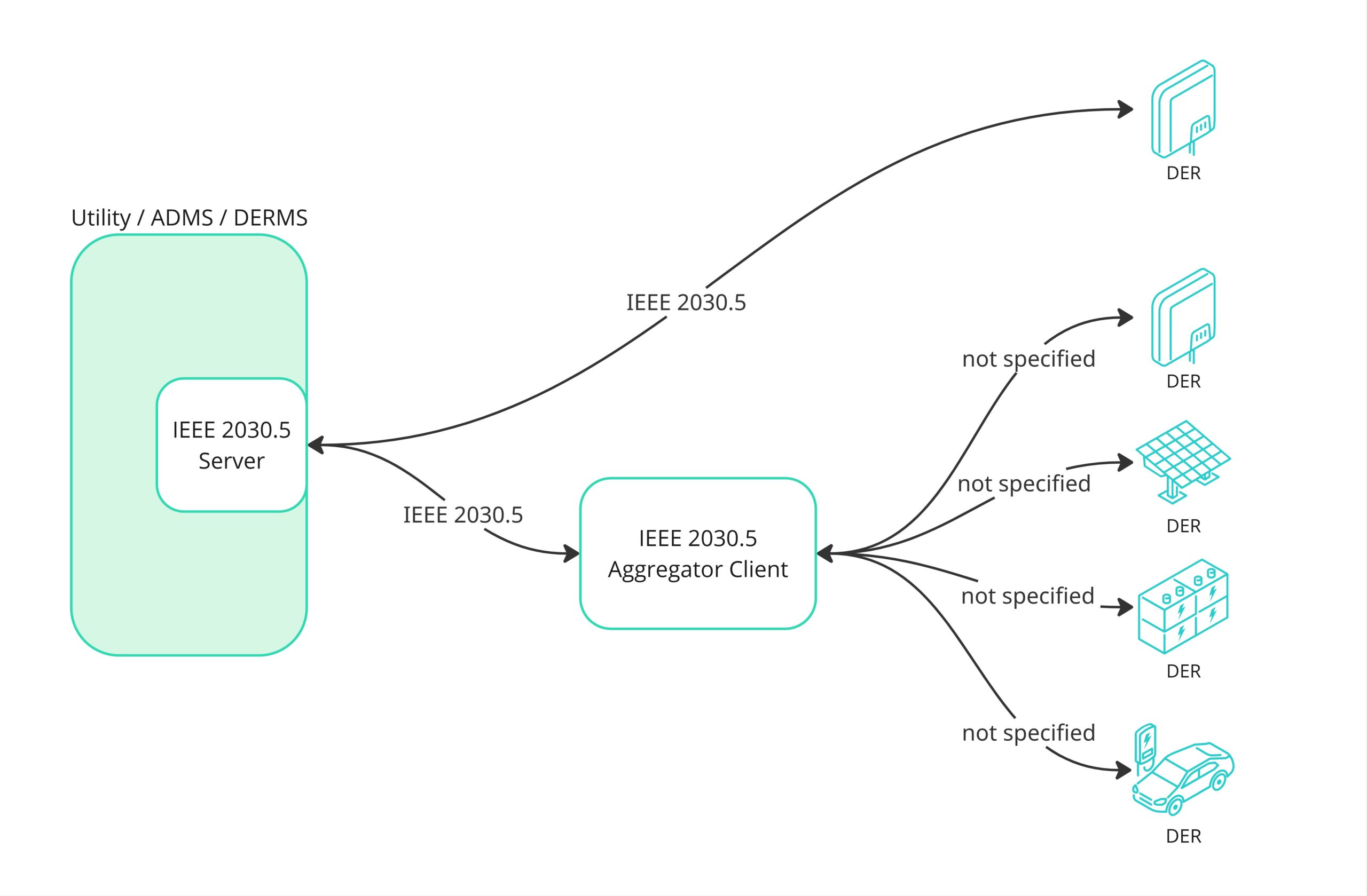
Reading the diagram from left to right: the utility’s ADMS or DERMS hosts a 2030.5 server. That server has two outbound paths, both labeled IEEE 2030.5. One arrow goes directly to a DER that runs a native 2030.5 client. That case is rare in practice, mostly grid-scale assets and a few modern smart inverters with CSIP-certified stacks. The second, far more common, goes to a 2030.5 aggregator client. Past the aggregator, the labels disappear: “not specified.” The aggregator may translate to OCPP for EV chargers, to Modbus for inverters and battery systems, or to a vendor cloud API for a fleet whose OEM owns the device-management layer. None of those southbound protocols are 2030.5.
The standard’s job is to absorb protocol diversity behind a single, predictable interface that the utility’s ADMS or DERMS can talk to. Everything else, the device protocols, the cloud APIs, the edge gateways, is integration work that varies by customer and by utility. That is the work that fills the engineering calendar long after certification is complete.
How California’s Attestation Route Shaped the Topology
E5000 did more than offer a second compliance pathway. It changed what a deployed system looks like. With the attestation route on the table, OEMs could ship inverters that did not natively run a 2030.5 client and still appear on the California-approved equipment list. The resulting topology is now the dominant pattern in Rule 21 deployments and in the markets that took cues from California: Utah and parts of Washington.
In that pattern, traffic flows from the utility’s 2030.5 server to a 2030.5 aggregator. The aggregator translates downstream to whatever protocol the local system actually understands, most often a SunSpec Modbus gateway sitting near the inverter, sometimes a vendor-specific cloud API, occasionally something proprietary that lives outside Rule 21’s scope. The boundary between aggregator and gateway is not standardized at the protocol level, which is precisely why the aggregator role exists.
For a utility designing a new interconnection program, this topology has practical implications. It means the utility cannot assume its 2030.5 server will speak directly to inverters. It means the test suite needs to cover aggregator behavior as much as device behavior. And it means the California Rule 21 implementation strategy has to plan for the gateway layer explicitly rather than treat it as an OEM concern.
The Server Side of the Boundary — What the Utility Has to Stand Up
On the utility side of the boundary, a production 2030.5 server is more than a protocol implementation. It is a cloud system that connects the utility’s existing operational platform, typically a DERMS, to the broader 2030.5 ecosystem of clients.
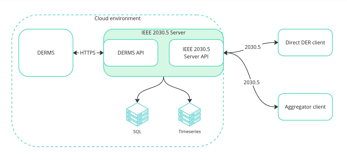
The DERMS sits on the left as the existing operational platform. It talks to the 2030.5 server over HTTPS through a dedicated DERMS API. That API is the integration seam where the customer-specific work happens; the 2030.5 spec defines the southbound surface, but the northbound surface, into the utility’s back office, varies by customer and depends entirely on whatever stack the utility already runs.
To the right of the server, two clients are shown: a direct DER client and an aggregator client. The server treats them identically at the protocol level, even though the integration patterns downstream of each look quite different. Below the server, two databases handle state: a relational SQL store for end-device records, group and program definitions, certificates, and the rest of the operational state, plus a time-series database that receives telemetry as it streams in.
A handful of common drivers send a utility down the path of standing this up. Regulatory compliance, Rule 21, AS/NZS 4777, and similar interconnection mandates, is the most visible. Onboarding third-party aggregators and VPP operators into utility programs is another, since a 2030.5 server replaces a sprawl of bilateral integrations with a single standard surface. Demand response and peak-curtailment programs, dynamic export limits under feeder constraints, and telemetry visibility into DER the utility does not own all push in the same direction.
The Client Side of the Boundary — What the Aggregator Actually Owns
The aggregator’s side of the boundary mirrors the server’s structurally, but the work concentrates somewhere different. Here, the standardized 2030.5 surface points northbound to the utility, while the southbound integration to actual assets is custom and varies project by project.
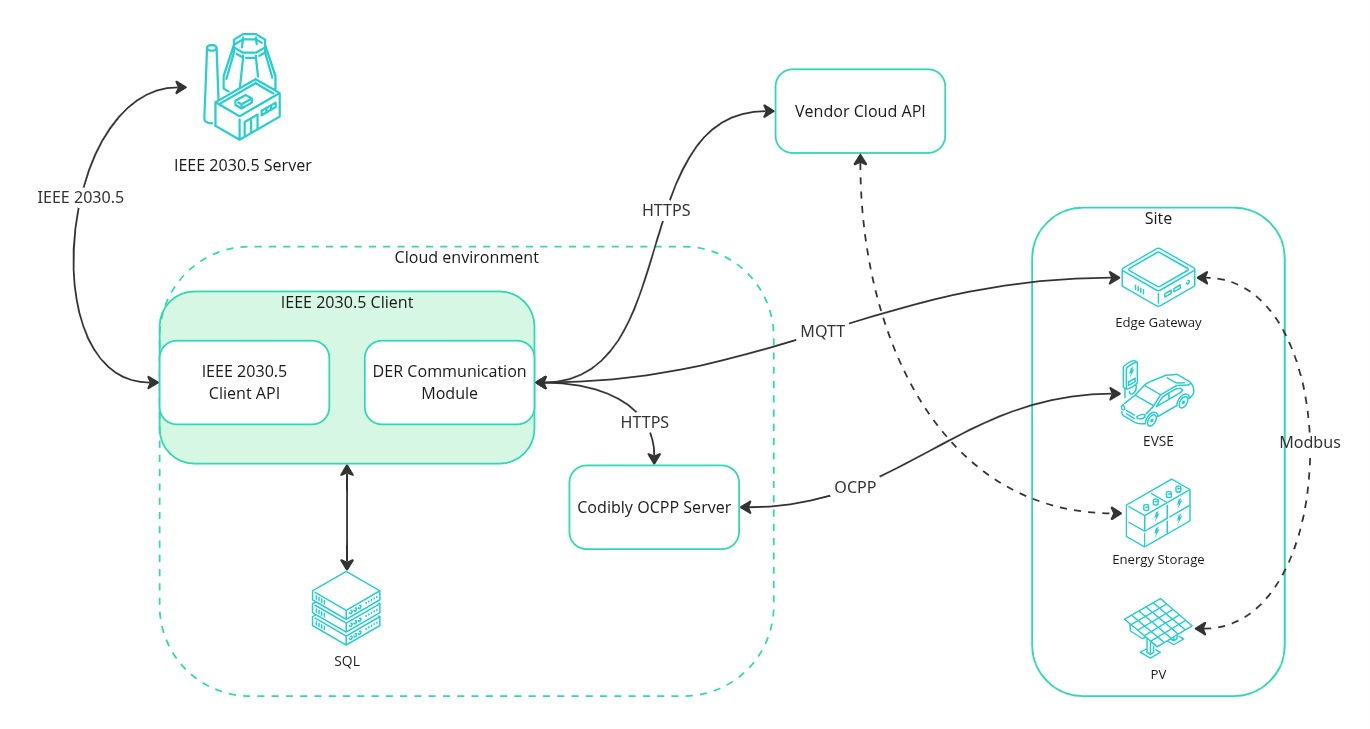
A typical aggregator client deployment combines three integration patterns, often more than one in the same fleet. The first is a vendor cloud API over HTTPS, the path used to reach a fleet of consumer batteries managed by their OEM cloud. The second is a managed-charging path: the client speaks to an OCPP server (Codibly ships its own as part of the accelerator family), which in turn speaks OCPP downstream to EV chargers. The third is an edge gateway over MQTT, where the gateway then talks SunSpec Modbus locally to inverters, batteries, and PV systems on the same site. That third pattern is the one most semantically aligned with 2030.5: SunSpec Modbus and 2030.5 share the same DER concepts and behaviors, which makes the translation work structurally simpler than it is for the cloud-API or OCPP options.
The 2030.5 client itself stays the same regardless of what sits on the right edge of the picture. The per-project work concentrates inside what Codibly calls the DER Communication Module, the southbound translator. That is where customer-specific code actually lives, and it is where simulation matters: a DER simulator that can stand in for multiple assets, react to events arriving from the utility, and generate realistic telemetry lets the integration be exercised end-to-end before any real device is connected.
This pattern is not California-specific. It also describes how 2030.5 is being deployed for V2G readiness across DSOs and fleet operators and how it sits inside the broader DR protocol-certification landscape alongside OpenADR and CTA-2045.
CSIP Is the Foundation. The Real Work Sits on Top.
CSIP gives every 2030.5 deployment a common floor. Above it, each utility adds its own rules, driven by the back office, by the specific program being run, or by the type of asset being integrated. Storage brings asset-specific controls. EV chargers bring their own constraints. Rooftop PV brings yet another set. None of those per-utility deltas are in CSIP itself, but every one is real code on the client side.
A concrete view of what those deltas look like comes from comparing two real utility requirement sets, a North American utility and an Australian distribution network service provider (DNSP):
| Category | North American utility | Australian DNSP |
|---|---|---|
| EndDevice modeling & registration | Single-site or aggregated EndDevices; in-band registration; LFDI derivation per CSIP baseline. | Single-site or aggregated EndDevices, including VPP-style aggregation with reporting-only members; in-band or out-of-band registration; LFDI derivation rules vary by market; explicit multi-DER aggregation rules. |
| Telemetry cadence | Per-DER metrics (real and active power, voltage, frequency) every 5 minutes alongside DER status, plus real-time alarm-status updates. In VPP setups, aggregated telemetry on top, including net active power for the whole fleet. | UTC-aligned post rates; underlying real and reactive power values calculated by hardware integration of energy over the post period (sampling as fallback). Specific to asset type. |
| Asset-specific telemetry | EVSE telemetry covers three-phase voltage and total real and reactive power; EV telemetry focuses on state of charge. | Storage-asset extensions for charge/discharge rate ratings and minimum energy floor; reporting on those fields aligned to AS/NZS 4777.2. |
| Capabilities & settings | Required fields for storage ratings and supported modes per CSIP; availability and event logging present but typically optional and contract-driven. | Required charge and discharge rate ratings and a minimum energy floor for storage assets; DERAvailability and LogEvent usage extended beyond the optional baseline. |
| DR controls & operations | DERControl events expected to reach the device within 5 minutes; minimum stored event count raised from 24 to 72; primacy and randomized-start behavior per CSIP. |
Storage control response within 15 seconds, aligned to AS/NZS 4777.2; adds OpModStorageTargetW operation mode for storage set points. |
| CSIP-AUS adoption | Optional, contract-driven where it appears. Explicit-limit fields are referenced in some managed-charging requirement sets but not mandatory. | Mandatory: opModImpLimW, opModExpLimW, and opModLoadLimW for managed-charging programs. |
The pattern across the table is consistent. CSIP supplies the protocol foundation; the utility-specific deltas across end-device modeling, telemetry, capabilities, and DER controls are where most of the integration effort actually concentrates. A 2030.5 deployment project does not fail at the spec layer. It fails when the project plan treats the per-utility handbook as an afterthought.
CSIP-AUS is worth singling out. It is an Australian extension that adds explicit import, export, and load-limit fields, specifically opModImpLimW, opModExpLimW, and opModLoadLimW. These were defined for the Australian market and align to AS/NZS 4777.2, but the explicit-limit semantics fit naturally into managed-charging programs elsewhere in the world, and they are creeping into requirement sets outside Australia. Codibly’s SolarEdge multi-DNSP integration in Australia is one of the projects where those fields live in production, alongside the BESS provider’s Rule 21 certification in California.
What the Cert Distribution Tells You About Where the Protocol Lives
Useful corroboration of the deployment topology comes from the certifications themselves. As of the SunSpec × Codibly session, the SunSpec ecosystem had performed roughly 57 client CSIP certifications, around 30 of those for aggregators, and 8 to 9 server certifications. Two things stand out in that distribution.
First, the ratio of clients to servers is about seven to one. That is consistent with a topology where each utility-side server is talking to many aggregator and OEM clients: a few large hubs, many smaller spokes. Second, the share of client certifications that are aggregator certifications, roughly half, confirms that the aggregator is a first-class participant in the protocol, not an afterthought. The bulk of 2030.5 traffic that actually moves between utilities and DERs in production crosses the aggregator boundary.
For a utility designing a program now, that means a 2030.5 server is closer to a market-access layer than to a device-management tool. For an aggregator or VPP operator, it means a 2030.5 client is the surface that determines which utility programs the fleet can join. For a hardware OEM, it means the architectural choice is between a native client at the device and a gateway-attested path: both legitimate, with different tradeoffs and different downstream consequences for product roadmaps.
From Compliance to Deployment — How to Plan an IEEE 2030.5 Project Now
The pragmatic takeaway from the deployment topology is that an IEEE 2030.5 project should be scoped around the seam each party actually owns. A utility owns the server and the DERMS API into its back office. An aggregator owns the 2030.5 client and the southbound DER Communication Module. An OEM owns the device stack and chooses between a native 2030.5 client and an attested-gateway pathway. The boundary between server and client is the standardized seam. Everything else is integration.
Three planning implications follow. Treat CSIP as the floor, not the ceiling: the per-utility handbook will define the work that comes after certification, and that work is rarely small. Plan for the deltas, telemetry cadences, control response times, registration rules, function-set extensions, before certification, not after, so the integration converges instead of accumulating rework. And use simulation aggressively: a DER simulator that can stand in for the asset mix the project actually involves catches misalignments cheaply, well before the utility’s own test environment exposes them.
Codibly’s pre-tested IEEE 2030.5 server and client accelerators collapse the protocol layer into a known quantity, so each project’s effort concentrates where it adds value: the DERMS API on the server side, the DER aggregation module on the client side, and the per-utility handbook in between. That model has supported deployments from California Rule 21 BESS certifications to multi-DNSP integrations in Australia, and it pairs naturally with the implementation discipline covered in Article 2’s pitfall analysis for DER manufacturers and the regulatory context laid out in Article 1’s national-trajectory piece.
Frequently Asked Questions
CSIP is a tailored subset of IEEE 2030.5 that defines the use cases and test cases relevant for smart inverters and other DERs. It was developed by the SunSpec Alliance to give utilities and inverter manufacturers a common way to satisfy California Rule 21 and similar interconnection mandates. CSIP defines required function sets, message exchanges, and certificate requirements; certification is performed against the SunSpec test suite.
Both are utility communication standards, but they target different layers of the grid. IEC 61850 was originally designed for substation automation and now extends to DER integration; it is widely used inside utility substations and for high-bandwidth communications between utility-owned assets. IEEE 2030.5, also known as Smart Energy Profile 2.0, is a system-level interface that uses Internet protocols (HTTPS, TLS) to let utilities talk to large fleets of consumer-scale and behind-the-meter DERs through aggregators or local clients. In a typical deployment, IEC 61850 and IEEE 2030.5 coexist: one inside the substation, the other on the path to distributed assets.
IEEE 2030.5 itself is the remote control and communication protocol. It uses RESTful HTTPS over TLS to let a utility-side server publish events, programs, and control schedules that DER clients subscribe to. The protocol defines resources for end-device registration, telemetry reporting (via MirrorUsagePoint), DER control events (DERControl), program assignments (FunctionSetAssignments), and the certificate-based authentication that secures the channel. CSIP narrows the broad IEEE 2030.5 spec to the specific function sets needed for smart inverter control.
CSIP-AUS is the Australian extension to CSIP. It adds explicit import, export, and load-limit fields, opModImpLimW, opModExpLimW, and opModLoadLimW, that the base CSIP profile leaves implicit. The fields were introduced for AS/NZS 4777.2-aligned deployments in Australia, but the explicit-limit semantics fit naturally into managed-charging and dynamic-export-limit programs elsewhere, so utility requirement sets outside Australia have started to reference them.
Utilities and DERMS vendors host a 2030.5 server. Aggregators, VPP operators, and OEMs that need to expose their fleet or device to a utility program implement a 2030.5 client. A single organization can need both, for example, a utility that also runs an aggregator-style program, but the more common case is a one-sided deployment matched to the participant’s role. Codibly’s accelerators provide both surfaces independently so each project can scope to the side of the boundary it actually owns.